LAMBDA project
Abstract
In the pursuit of lighter materials and optimized thin-walled components for transportation, knowledge about the characteristic ductile damage mechanisms in metal sheets is key. As the study of damage in materials has, up to now, been focused on proportional loading, the strain-damage interaction is not understood for the highly application-relevant bi-axial loading with load path changes. Thus, the LAMBDA project aims at three-dimensional (3D) imaging of the microstructure inside flat sheet specimens evolving during material testing under such loads. For this, we extend the capability of in situ synchrotron radiation computed laminography (SRCL) to overcome inherent insufficiency of other 3D techniques for such kind of samples. The methodology shall be developed into a unique multi-scale approach from a few hundred micrometers down to nanometer scale to determine the ductile damage nucleation and growth kinetics. Such hierarchical 3D data will serve as valuable input for microscopic simulations and the formulation and validation of continuum damage models suited to predict engineering-relevant mechanical properties.
Partners
ARMINES / Centre des Matériaux Mines ParisTech
KIT: CN-IPS Karlsruhe Institute of Technology, Institute for Photon Science and Synchrotron Radiation
KIT: CS-LAS (University) Karlsruhe Institute of Technology, Laboratory for Applications of Synchrotron Radiation
Funding
Funded by ANR and DFG
Project ID: ANR-17-CE08-0051
Background
Synchrotron Radiation Computed Laminography (SRCL)
Synchrotron radiation-computed laminography (SRCL) is a technique for non-destructive 3D imaging of regions of interests optimized for laterally extended (i.e. in the sheet directions perpendicular to the rotation axis) specimens [1,2] . The technique acquires projection data sets similar to synchrotron computed tomography (SRCT), but it uses an inclined rotation axis at an angle θ < 90° instead of being perpendicular to the incoming beam (see Figure 1). This feature allows SRCL to avoid projections with corrupted information for view directions, for which the transmission would locally tend to zero due to a long beam path within the sample or its environment.
Due to its specifities, SRCL has found exciting new applications for micro- and nano-imaging in different application fields such as electronic devices, organic tissues, paintings, or paleontological specimens. This technique is especially useful when it is required or desirable to leave the flat sample intact, either for non-destructive purposes or when the sample needs to be studied in its natural environment. Within the framework of an international collaboration, the instruments installed by the partners at the KARA storage ring at KIT and at the European Synchrotron Radiation Facility (ESRF) take advantage of the beamline characteristics for absorption and phase-contrast laminography (ESRF ID19), fast white-beam laminography (ESRF ID15A and KIT IMAGE), and nano-scale phase-contrast and fluorescence laminography (ESRF ID16B) [3]. Algorithms developed in-house enable laminography to image and reconstruct large regions of interest (which considerably exceed the detector size) of the sample with high resolution by combining several scans carried out at adjacent sample positions.

Damage evolution during straining
Prior porosity and brittle intermetallic phases are widely established as critical to the damage tolerance characteristics of most structural engineering alloys. Damage evolution has been successfully observed in situ in 3D via SRCT, typically using specimens with a cross-section of up to a few square millimeters. However, plastic zone sizes and stress triaxiality levels are not representative of the sustained macroscopic crack extension associated with many key engineering failure situations. With recent developments in SRCL, it has become possible to perform in situ high-resolution 3D imaging on objects that are extended in two dimensions, i.e. the sheet or plate-like sample geometries.
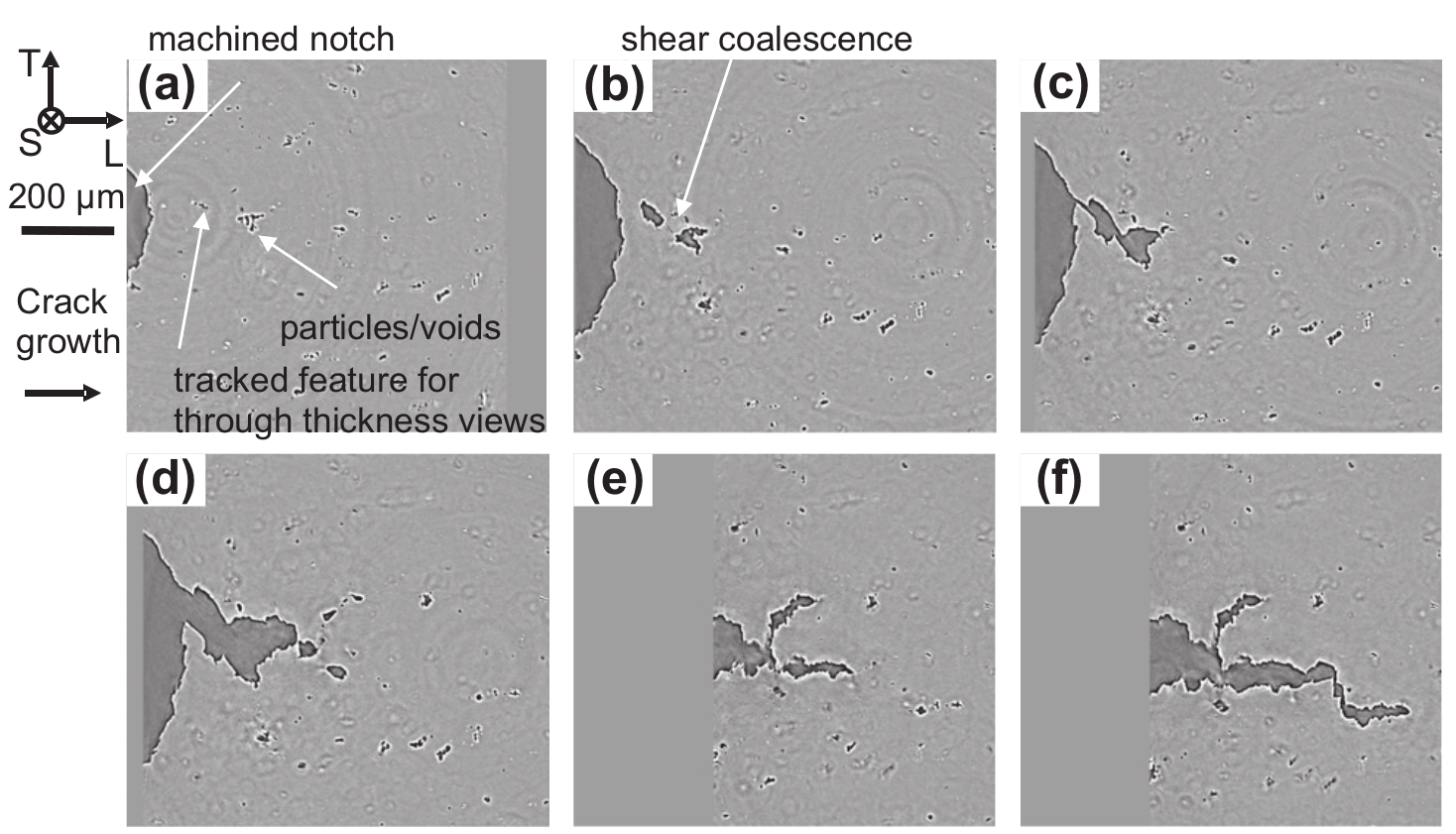
The example of such studies is demonstrated in Figure 2 and Figure 3. The used sample geometry and loading device are shown in Figure 2 (a), while the visualization of the reconstructed 3D laminography data around the notch before and after deformation are presented in Figure 2 (b–c). Reconstructed 2D laminography sections in the sheet plane at about the mid-thickness of the sample are shown in Figure 3, with Figure 3 (a) showing the as-received material and (b–f) corresponding to different loading stages.


References
[1] Helfen, L., et al. "High-resolution three-dimensional imaging of flat objects by synchrotron-radiation computed laminography." Applied Physics Letters 86.7 (2005): 071915.
[2] Helfen, L., et al. "On the implementation of computed laminography using synchrotron radiation." Review of Scientific Instruments 82.6 (2011): 063702.
[3] https://www.anka.kit.edu/974_1109.php
[4] Morgeneyer, Thilo F., et al. "In situ 3-D observation of early strain localization during failure of thin Al alloy (2198) sheet." Acta Materialia 69 (2014): 78-91.
[5] Morgeneyer, Thilo F., et al. "Ductile crack initiation and propagation assessed via in situ synchrotron radiation-computed laminography." Scripta Materialia 65.11 (2011): 1010-1013.